
Views: 24 Author: David Cianciolo Publish Time: 2022-09-24 Origin: connector supplier

Cable assemblies streamline the design, procurement, production, testing, and installation process. They simplify supply chains and reduce cost. These pre-assembled component solutions are frequently used in military and aerospace, medical, heavy equipment, and industrial applications, as their designs can be specified to meet challenging requirements, such as extreme environments, sterilization, and electromagnetic interference. They also provide flexibility and weight reduction and can include active electronic components and options like bend reliefs and sealing caps.
Cable assemblies allow OEMs to deal with a single trusted cable assembly partner instead of sourcing connectors, cables, and accessories individually. This approach reduces bill-of-materials entries and reduces costs by 15-30% over separate component purchases. Production flow and cost are also simplified. Instead of investing in the manpower, expertise, tooling, and supplies required to create robust cable assemblies in house, custom cable assembly solutions arrive finished, tested, and ready to install.
Identify the application and its requirements early in the design process to avoid over-designing cable assemblies that cost too much or under-designing cable assemblies that fail to meet the system’s requirements.
The electrical requirements of an application are key to conductor size selection. The conductor size should be selected based on the necessary power load of the application. Ambient temperature always needs to be taken into consideration when selecting the conductor size of the cable. The ampacity of a conductor and its correction factor are defined based on ambient temperature and the number of conductors.
Copper is used on most assembly applications. However, various copper alloys offer unique benefits, including increased hardness, tensile strength, flex endurance, and temperature resistance — although some alloys sacrifice electrical conductivity. Alloys are well-suited for fine-gauge applications (28 AWG or smaller).
The conductor material and the conductors’ stranding affect the flex life of a cable. High-tensile-strength alloys exhibit longer flex life. Strand construction also has an effect on the overall flexibility of a conductor or cable. Higher flexibility, achieved by finer stranding, leads to longer life.
The circular mil is the wire cross-sectional area used in American and British wire tables. The circular mil area (CMA) is the area of a circle one mil (one-thousandth of an inch) in diameter. Therefore, the area of a circle in circular mils is equal to the square of its diameter.
While solid conductors (single-strand) are available, most assemblies are designed using stranded wire, consisting of many fine strands of wire twisted together. The gauge assigned to such a conductor is determined by the total cross-sectional area of all the individual strands added together. Stranded conductors are used where flexibility is needed. Flexibility varies based on conductor construction: bunched lay, unilay, rope lay, and concentric.
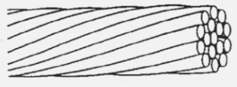 Bunched Lay:Any number of strands in a random pattern. Twisted in one operation, all strands have the same lay direction and same lay length. However, the result is a rougher surface and lower dimensional tolerance than concentric constructions. The number of strands is determined by the size of the individual strands and the total cross-sectional area required. Bunched lay conductors are the most common, as they provide optimum flexibility which is typically desired in a cable design.
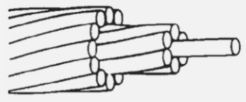 Unilay: Central wire surrounded by one or more layers of helically laid wires in a geometric pattern, with the same lay direction and the same lay length. In unilay cable design the strands are typically larger in diameter. Unilay conductors are the next most common and they bring good flexibility and a slightly lower cost than bunched lay.
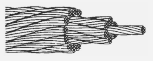 Rope Lay: Single strands assembled into concentric or bunched configurations. Rope stranding cable design has the advantage of increasing flexibility by using a larger number of finer strands while maintaining a tighter diameter tolerance than a simple bunched construction. Constructions vary and can contain thousands of strands. Rope lay conductors are most flexible, but require multiple twisting operations which bring extra cost, lower copper density, and larger diameter. Rope lay conductors are typically sold as single conductors and not typically used in multi-conductor cables.
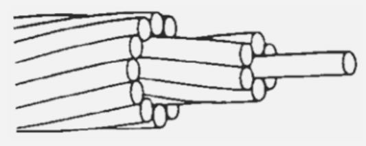 Concentric Lay: Central wire surrounded by multiple layers of helically laid wires with alternately reversed lay direction and increasing lay lengths. Concentric lay conductors are not very common; they are the roundest conductor type (besides solid), which is good for electrical purposes where concentricity of the insulation wall is critical.
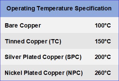
High-humidity environments cause copper to quickly oxidize. The most common plating options to prevent oxidation are tin, silver, and nickel plating. Tin and silver plating prevent copper oxidation and corrosion and improve the solderability and termination of the conductors. If the application is in a high-temperature environment, silver or nickel plating is the best choice to protect the conductors.
The majority of insulation materials fall into two groups: rubbers and thermoplastics.
Rubber is normally used in the 0-600 volt range. They offer good flexibility, tear strength, and water resistance but have limited resistance to oils and hydrocarbon fuel. Silicone offers excellent thermal ratings, a thermal range of -60°C to 180°C, and medium abrasion and cut resistance. Neoprene offers very good weathering properties, resistance to oil, flame, and ozone, and good mechanical toughness. PVC is available in many varieties and formulations. It is generally inexpensive but not ideal for high-temperature or high-speed data applications. Fluorocarbons (FEP, PFA, PTFE, ETFE) are more expensive but offer high temperature ratings, a low dielectric constant, and ETFE offers excellent cold-flow characteristics and radiation resistance.
Cable shielding is available in three types: braid, serve/spiral, and foil. Shielding is a conductive barrier that surrounds the insulated wires inside a cable. The purpose of a shield is to prevent noise emitted from other nearby cables or electronics, and even noise emitted from adjacent wires within a cable, from interrupting signals within the cable. It also prevents electromagnetic interference (EMI) from radiating out of the cable. Shielding effectiveness is the shield’s ability to prevent EMI passing in or out of the cable. Foil in combination with a braided shield provides the best of both worlds. It combines the shielding effectiveness of the foil shield with the flex life of the braid.
Good overall shielding effectiveness for a cable assembly is achieved only if the shield is properly terminated to the connector, on both ends of the assembly. As a rule, the overall shielding effectiveness will be dictated by the size of the largest opening throughout the assembly; the smaller the better. Shield coverage openings often occur at the cable to connector transition. It is important to maintain 360° coverage across the full length of the cable assembly.
Fillers are used to fill in gaps in the cable construction to improve the roundness of a multi-conductor cable. This facilitates overmolding of a cable. Fillers improve the durability and flex life of a cable. Fillers can also be used to prevent fluid entry into a cable. Common filler materials are cotton strings or yarn, extruded thermoplastic, and foam.
Tapes and wraps, also referred to as separators, can offer noise suppression and reduce cross-talk between cable components. The most commonly used materials are:
Paper tape: Used between cable jackets and shield to facilitate ease of cable jacket removal. It is also very inexpensive.
PTFE tape: Also used between cable jackets and shield. PTFE tape provides abrasion resistance, uniformity and performance. PTFE tape is often used to reduce loss in high-speed data cables.
Mylar tape: Excellent tensile strength and durability, used as cable insulation. With an operating temperature of 150°C.
Kapton tape: Mechanically tough, abrasion and cut-through resistant. It also improves a cable’s weather resistance. It has an operating temperature range of -200°C to +200°C. Kapton is radiation resistant and will not burn. Kapton also has excellent electrical properties.
A strength member is a component within the cable that provides added tensile strength to a cable and removes the stress from the conductors. It is critical to position the strength member as close to the center of the cable as possible to relieve the stresses applied to the cable. Typically made of aramid fiber (Kevlar), a strength member is added to increase the overall strength of a cable assembly. Aramid fiber is a strong material ideal for increasing the tensile strength of cables. It is available in a variety of configurations with varying break strengths. For example, a .034 in. x .024 in. (.86 mm x .61 mm) aramid fiber has a break strength of 120 lbs (540 N). When selecting a strength member, ask what pull strength is required and if the strength member needs to be terminated to the connector.
Defining connector requirements is just as important as defining the cable requirements. Connectors must be compatible with the cable, and vice versa.
Consider the environment the cable assembly will be used in. The connector manufacturer will be the best source of technical support regarding:
Connector durability and weight
EMI & RFI shielding available
Connector pull-out strength
Overmolding cable assemblies
Overmold geometries available
Electrical requirements; voltage hold-off, current carrying capabilities, insulation resistance, data-transmission rates
Electrical and leak-seal testing
Connector / cable thermal capabilities
Cable / connector assembly sealing
Bend reliefs available
Number of connector mating cycles
Connector materials
The two major types of wire / contact terminations are crimp and solder. Crimp termination is achieved with automated machinery and provides reliable terminations only when using stranded conductors. Special crimp tooling and dies are required and a limited range of conductor sizes can be used. Solder termination provides reliable terminations using solid or stranded conductors. No special tooling is required and a wider range of conductor sizes can be used, but more skill is required to terminate reliably.
The cable entry to the connector needs to be secured to prevent premature cable breakage. Overmolds and heat-shrink tubing provide some strain relief at the junction of the cable to the connector. Overmolding should not be relied upon as the only strain relief. The most basic options are the two- piece cable clamp or the collet. The latter is the more effective option of the two. Both are connector components and both provide cable-strain relief. If a bend relief is also needed to reduce cable-bend stresses at the connector exit, consider heat shrink or a pre-molded bend relief. These are usually offered by the connector manufacturer. A custom overmold can also provide bend relief and give a very finished appearance to the cable assembly.
The connector and cable entry may need to be protected from fluid ingress. Overmolds and heat-shrink tubing provide sealing at the junction of the connector and the cable. Adhesive-lined heat-shrink tubing offers moderate resistance to moisture. A better solution is overmolding the cable and connector. The mating surface of the connector may also need to be sealed; this will require additional sealing processes within the connector. Each connector sealing requires a specialized product, process and test method to ensure that a reliable and high-quality sealed product is produced
Understanding the end-use application and its environment is crucial to the overall interconnect solution design. By considering each of the 16 key factors surrounding an application design and function, the cable assembly engineer can select the most appropriate materials to ensure optimal performance.


